| |
MOORING BRIDLE PLATE
OR PADEYE DESIGN VERIFICATION
|
|
| |
Padeye Check
|
|
|
|
| |
1) GEOMETRY
|
|
|
| |
|
|
|
| |
|
|
|
| |
|
|
|
| |
|
|
|
| |
|
|
|
| |
|
|
|
| |
|
|
|
| |
|
|
|
| |
|
|
|
| |
|
|
|
| |
|
|
|
| |
|
|
|
| |
|
|
|
| |
|
|
|
| |
|
|
|
| |
|
|
|
| |
|
|
|
| |
|
|
|
| |
|
|
|
| |
|
|
|
| |
|
|
|
| |
|
|
|
| |
|
|
|
| |
|
|
|
| |
|
|
|
| |
Figure : Padeye
|
|
|
|
Figure: shackle
|
|
| |
|
|
|
|
|
|
| |
Padeye
|
|
|
|
|
|
| |
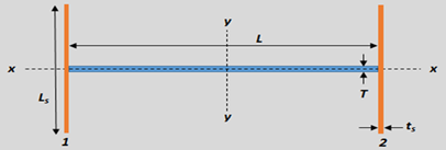
Length of Main Plate, L
|
|
|
|
mm
|
|
| |
Thickness of Main Plate,T
|
|
|
|
mm
|
|
| |
Height to Pinhole, LA
|
|
|
|
mm
|
|
| |
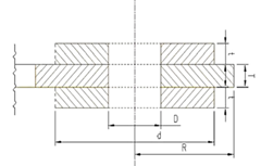
Diameter of Padeye hole, D =
|
|
|
|
mm
|
|
| |
Radius of Padeye, R
|
|
|
|
mm
|
|
| |
Diameter of Cheek Plate, dcheek
|
|
|
|
mm
|
|
| |
Thickness of Cheek Plate, tcheek
|
|
|
|
mm
|
|
| |
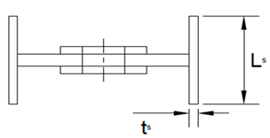
Stiffener Length, Ls
|
|
|
|
mm
|
|
| |
Stiffener Thickness, ts
|
|
|
|
mm
|
|
| |
Shackle
|
|
|
|
|
|
| |
Internal Length, C
|
|
|
|
mm
|
|
| |
Internal Width, A
|
|
|
|
mm
|
|
| |
Eye Diameter, F
|
|
|
|
mm
|
|
| |
Pin Diameter, B
|
|
|
|
mm
|
|
| |
2) INPUT FORCES
|
|
|
|
|
|
| |
|
|
|
|
| |
|
|
|
| |
|
|
|
| |
|
|
|
| |
|
|
|
| |
|
|
|
| |
|
|
|
| |
|
|
|
| |
|
|
|
| |
|
|
|
| |
|
|
|
| |
|
|
|
|
|
|
| |
|
|
|
|
|
|
| |
|
|
|
|
|
|
| |
|
|
|
|
|
|
| |
|
|
|
|
|
|
| |
|
|
|
|
|
|
| |
Pulling Load on Pullhead (Padeye), Fpull
|
|
|
|
MT
|
|
| |
In-plane angle, α
|
|
|
|
deg
|
|
| |
Out-of-plane angle, β
|
|
|
|
deg
|
|
| |
Padeye Material Yield Stress, Fyield,padeye
|
|
|
|
MPa
|
|
| |
Material Young's Modulus, E
|
|
|
|
MPa
|
|
| |
3) RESULTS SUMMARY
|
|
|
|
|
|
| |
Bearing Stress
|
|
|
|
|
|
| |
Block Shear
|
|
|
|
|
|
| |
Cheek Plate Weld Stress
|
|
|
|
|
|
| |
Shear Stress in Section A-A
|
|
|
|
|
|
| |
Tensile Stress Section B-B
|
|
|
|
|
|
| |
|
|
|
|
|
|
| |
4) CALCULATIONS
|
|
|
|
|
|
| |
Bearing Stress
|
|
|
|
|
|
| |
Allowable Bearing Stress, 0.9Fyield
|
|
|
|
MPa
|
|
| |
Bearing Stress
|
|
|
|
MPa
|
|
| |
Ratio
|
|
|
|
|
|
| |
Block Shear
|
|
|
|
|
|
| |

|
|
|
|
|
|
| |
|
|
|
|
|
|
| |
|
|
|
|
|
|
| |
|
|
|
|
|
|
| |
|
|
|
|
|
|
| |
|
|
|
|
|
|
| |
|
|
|
|
|
|
| |
|
|
|
|
|
|
| |
Ratio
|
|
|
|
|
|
| |
Cheek Plate Weld Stress
|
|
|
|
|
|
| |
Min Weld Thickness Required
|
|
|
|
mm
|
|
| |
Weld Thickness
|
|
|
|
mm
|
|
| |
Effective Weld Thickness, t,weld
effective
|
|
|
|
mm
|
|
| |
Weld Stress
|
|
|
|
MPa
|
|
| |
Ratio
|
|
|
|
|
|
| |
Shear Stress in Section A-A
|
|
|
|
|
|
| |
|
|
|
|
|
|
| |
|
|
|
|
|
| |
|
|
|
|
|
| |
|
|
|
|
|
| |
|
|
|
|
|
| |
|
|
|
|
|
| |
|
|
|
|
|
| |
Allowable Shear Stress, 0.4Fyield
|
|
|
|
MPa
|
|
| |
Shear Stress in Section A-A
|
|
|
|
MPa
|
|
| |
Ratio
|
|
|
|
|
|
| |
Tensile Stress in Section B-B
|
|
|
|
|
|
| |
|
|
|
|
|
|
| |
|
|
|
|
|
|
| |
|
|
|
|
|
|
| |
|
|
|
|
|
|
| |
|
|
|
|
|
|
| |
|
|
|
|
|
|
| |
|
|
|
|
|
|
| |
|
|
|
|
|
|
| |
Allowable Tensile Stress, 0.6Fyield
|
|
|
|
MPa
|
|
| |
Tensile Stress in Section B-B =
|
|
|
|
MPa
|
|
| |
Ratio
|
|
|
|
|
|
| |
|
|
|
|
|
|
| |
Combined Stress in Section CC
|
|
|
|
|
|
| |
|
|
|
|
|
|
| |
|
|
|
|
|
|
| |
|
|
|
|
|
|
| |
|
|
|
|
|
|
| |
|
|
|
|
|
|
| |
|
|
|
|
|
|
| |
|
|
|
|
|
|
| |
|
|
|
|
|
|
| |
|
|
|
|
|
|
| |
|
|
|
|
|
|
| |
|
|
|
|
|
|
| |
|
|
|
|
|
|
| |
Shear Force, F2
|
|
|
|
kN
|
|
| |
Shear Stress, σshear
|
|
|
|
MPa
|
|
| |
Ratio
|
|
|
|
|
|
| |
Allowable Bending Stress, 0.6Fyield
|
|
|
|
MPa
|
|
| |
In-Plane Bending Stress, σip
|
|
|
|
MPa
|
|
| |
Ratio
|
|
|
|
|
|
| |
Allowable Bending Stress, 0.6Fyield
|
|
|
|
MPa
|
|
| |
Out-of-Plane Bending Stress, σop
|
|
|
|
MPa
|
|
| |
Ratio
|
|
|
|
|
|
| |
Unity Check
|
|
|
|
|
|
| |
Padeye Weld Check
|
|
|
|
|
|
| |
Thickness of baseplate/ deck, tbase
|
|
|
|
mm
|
|
| |
Min Weld Thickness Required
|
|
|
|
mm
|
|
| |
Weld Thickness, tweld
|
|
|
|
|
|
| |
Effective Weld Thickness, t,weld
effective
|
|
|
|
mm
|
|
| |
Shear Stress in Weld
|
|
|
|
MPa
|
|
| |
Ratio
|
|
|
|
|
|
| |
|
|
|
|
|
|